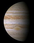
Near-Infrared Mapping Spectrometer
The Jet Propulsion Laboratory built the Galileo spacecraft and managed the Galileo program for NASA. West Germany's Messerschmitt-Bölkow-Blohm supplied the propulsion module. NASA's Ames Research Center managed the atmospheric probe, which was built by Hughes Aircraft Company. At launch, the orbiter and probe together had a mass of 2,562 kg (5,648 lb) and stood 6.15 m (20.2 ft) tall.
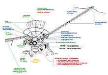
Spacecraft are normally stabilized either by spinning around a fixed axis or by maintaining a fixed orientation with reference to the Sun and a star. Galileo did both. One section of the spacecraft rotated at 3 revolutions per minute, keeping Galileo stable and holding six instruments that gathered data from many different directions, including the fields and particles instruments.
Galileo was intentionally destroyed in Jupiter's atmosphere on September 21, 2003. The next orbiter to be sent to Jupiter was Juno, which arrived on July 5, 2016.
Development
Jupiter is the largest planet in the Solar System, with more than twice the mass of all the other planets combined. Consideration of sending a probe to Jupiter began as early as 1959. NASA's Scientific Advisory Group (SAG) for Outer Solar System Missions considered the requirements for Jupiter orbiters and atmospheric probes. It noted that the technology to build a heat shield for an atmospheric probe did not yet exist, and facilities to test one under the conditions found on Jupiter would not be available until 1980. NASA management designated the Jet Propulsion Laboratory (JPL) as the lead center for the Jupiter Orbiter Probe (JOP) project. The JOP would be the fifth spacecraft to visit Jupiter, but the first to orbit it, and the probe would be the first to enter its atmosphere.

An important decision made at this time was to use a Mariner program spacecraft like that used for Voyager for the Jupiter orbiter, rather than a Pioneer. Pioneer was stabilized by spinning the spacecraft at 60 rpm, which gave a 360-degree view of the surroundings, and did not require an attitude control system. By contrast, Mariner had an attitude control system with three gyroscopes and two sets of six nitrogen jet thrusters. Attitude was determined with reference to the Sun and Canopus, which were monitored with two primary and four secondary sensors. There was also an inertial reference unit and an accelerometer. This allowed it to take high-resolution images, but the functionality came at a cost of increased weight. A Mariner weighed 722 kilograms (1,592 lb) compared to just 146 kilograms (322 lb) for a Pioneer.
John R. Casani, who had headed the Mariner and Voyager projects, became the first project manager. He solicited suggestions for a more inspirational name for the project, and the most votes went to "Galileo" after Galileo Galilei, the first person to view Jupiter through a telescope. His 1610 discovery of what is now known as the Galilean moons orbiting Jupiter was important evidence of the Copernican model of the solar system. It was also noted that the name was that of a spacecraft in the Star Trek television show. The new name was adopted in February 1978.
The Jet Propulsion Laboratory built the Galileo spacecraft and managed the Galileo mission for NASA. West Germany's Messerschmitt-Bölkow-Blohm supplied the propulsion module. NASA's Ames Research Center managed the atmospheric probe, which was built by Hughes Aircraft Company. At launch, the orbiter and probe together had a mass of 2,562 kg (5,648 lb) and stood 6.15 m (20.2 ft) tall. Spacecraft are normally stabilized either by spinning around a fixed axis or by maintaining a fixed orientation with reference the Sun and a star; Galileo did both. One section of the spacecraft rotated at 3 revolutions per minute, keeping Galileo stable and holding six instruments that gathered data from many different directions, including the fields and particles instruments. Back on the ground, the mission operations team used software containing 650,000 lines of code in the orbit sequence design process; 1,615,000 lines in the telemetry interpretation; and 550,000 lines of code in navigation. All of the spacecraft components and spare parts received a minimum of 2,000 hours of testing. The spacecraft was expected to last for at least five years—long enough to reach Jupiter and perform its mission.
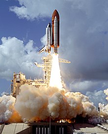
On December 19, 1985, it departed the JPL in Pasadena, California, on the first leg of its journey, a road trip to the Kennedy Space Center in Florida. Due to the Space Shuttle Challenger disaster, the May launch date could not be met. The mission was rescheduled to October 12, 1989. The Galileo spacecraft would be launched by the STS-34 mission in the Space Shuttle Atlantis. As the launch date of Galileo neared, anti-nuclear groups, concerned over what they perceived as an unacceptable risk to the public's safety from the plutonium in the Galileo's radioisotope thermoelectric generators (RTGs) and General Purpose Heat Source (GPHS) modules, sought a court injunction prohibiting Galileo's launch. RTGs were necessary for deep space probes because they had to fly distances from the Sun that made the use of solar energy impractical.
The launch was delayed twice more: by a faulty main engine controller that forced a postponement to October 17, and then by inclement weather, which necessitated a postponement to the following day, but this was not a concern since the launch window extended until November 21. Atlantis finally lifted off at 16:53:40 UTC on October 18, and went into a 343-kilometer (213 mi) orbit. Galileo was successfully deployed at 00:15 UTC on October 19. Following the IUS burn, the Galileo spacecraft adopted its configuration for solo flight, and separated from the IUS at 01:06:53 UTC on October 19. The launch was perfect, and Galileo was soon headed towards Venus at over 14,000 km/h (9,000 mph). Atlantis returned to Earth safely on October 23.
Command and Data Handling (CDH)
The CDH subsystem was actively redundant, with two parallel data system buses running at all times. Each data system bus (a.k.a. string) was composed of the same functional elements, consisting of multiplexers (MUX), high-level modules (HLM), low-level modules (LLM), power converters (PC), bulk memory (BUM), data management subsystem bulk memory (DBUM), timing chains (TC), phase locked loops (PLL), Golay coders (GC), hardware command decoders (HCD) and critical controllers (CRC).
The CDH subsystem was responsible for maintaining the following functions:
- decoding of uplink commands
- execution of commands and sequences
- execution of system-level fault-protection responses
- collection, processing, and formatting of telemetry data for downlink transmission
- movement of data between subsystems via a data system bus.
The spacecraft was controlled by six RCA 1802 COSMAC microprocessor CPUs: four on the spun side and two on the despun side. Each CPU was clocked at about 1.6 MHz, and fabricated on sapphire (silicon on sapphire), which is a radiation-and static-hardened material ideal for spacecraft operation. This 8-bit microprocessor was the first low-power CMOS processor chip, similar to the 6502 that was being built into the Apple II desktop computer at that time.
The Galileo Attitude and Articulation Control System (AACSE) was controlled by two Itek Advanced Technology Airborne Computers (ATAC), built using radiation-hardened 2901s. The AACSE could be reprogrammed in flight by sending the new program through the Command and Data Subsystem. The attitude control system software was written in the HAL/S programming language, which was also used in the Space Shuttle program.
Memory capacity provided by each BUM was 16K of RAM, while the DBUMs each provided 8K of RAM. There were two BUMs and two DBUMs in the CDH subsystem and they all resided on the spun side of the spacecraft. The BUMs and DBUMs provided storage for sequences and contain various buffers for telemetry data and interbus communication. Every HLM and LLM was built up around a single 1802 microprocessor and 32K of RAM (for HLMs) or 16K of RAM (for LLMs). Two HLMs and two LLMs resided on the spun side while two LLMs were on the despun side. Thus, total memory capacity available to the CDH subsystem was 176K of RAM: 144K allocated to the spun side and 32K to the despun side. Each HLM was responsible for the following functions:
- uplink command processing
- maintenance of the spacecraft clock
- movement of data over the data system bus
- execution of stored sequences (time-event tables)
- telemetry control
- error recovery including system fault-protection monitoring and response.
Each LLM was responsible for the following functions:
- collect and format engineering data from the subsystems
- provide the capability to issue coded and discrete commands to spacecraft users
- recognize out-of-tolerance conditions on status inputs
- perform some system fault-protection functions.
Propulsion
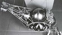
The propulsion subsystem consisted of a 400 N (90 lbf) main engine and twelve 10 N (2.2 lbf) thrusters, together with propellant, storage and pressurizing tanks and associated plumbing. The 10 N thrusters were mounted in groups of six on two 2-meter (6.6 ft) booms. The fuel for the system was 925 kg (2,039 lb) of monomethylhydrazine and nitrogen tetroxide. Two separate tanks held another 7 kg (15 lb) of helium pressurant. The propulsion subsystem was developed and built by Messerschmitt-Bölkow-Blohm and provided by West Germany, the major international partner in Project Galileo.
Electrical power
At the time, solar panels were not practical at Jupiter's distance from the Sun; the spacecraft would have needed a minimum of 65 square meters (700 sq ft) of panels. Chemical batteries would likewise be prohibitively large due to technological limitations. The solution was two radioisotope thermoelectric generators (RTGs) which powered the spacecraft through the radioactive decay of plutonium-238. The heat emitted by this decay was converted into electricity through the solid-state Seebeck effect. This provided a reliable and long-lasting source of electricity unaffected by the cold environment and high-radiation fields in the Jovian system.
Each GPHS-RTG, mounted on a 5-meter long (16 ft) boom, carried 7.8 kilograms (17 lb) of Pu. Each RTG contained 18 separate heat source modules, and each module encased four pellets of plutonium(IV) oxide, a ceramic material resistant to fracturing. The plutonium was enriched to about 83.5 percent plutonium-238. The modules were designed to survive a range of potential accidents: launch vehicle explosion or fire, re-entry into the atmosphere followed by land or water impact, and post-impact situations. An outer covering of graphite provided protection against the structural, thermal, and eroding environments of a potential re-entry into Earth's atmosphere. Additional graphite components provided impact protection, while iridium cladding of the RTGs provided post-impact containment. The RTGs produced about 570 watts at launch. The power output initially decreased at the rate of 0.6 watts per month and was 493 watts when Galileo arrived at Jupiter.
Telecommunications
The spacecraft had a large high-gain antenna which failed to deploy while in space, so the low-gain antenna was used instead, although at slower data transfer speeds.
Instruments
Scientific instruments to measure fields and particles were mounted on the spinning section of the spacecraft, together with the main antenna, power supply, the propulsion module and most of Galileo's computers and control electronics. The sixteen instruments, weighing 118 kg (260 lb) altogether, included magnetometer sensors mounted on an 11 m (36 ft) boom to minimize interference from the spacecraft; a plasma instrument for detecting low-energy charged particles and a plasma-wave detector to study waves generated by the particles; a high-energy particle detector; and a detector of cosmic and Jovian dust. It also carried the Heavy Ion Counter, an engineering experiment to assess the potentially hazardous charged particle environments the spacecraft flew through, and an extreme ultraviolet detector associated with the UV spectrometer on the scan platform.
The despun section's instruments included the camera system; the near infrared mapping spectrometer to make multi-spectral images for atmospheric and moon surface chemical analysis; the ultraviolet spectrometer to study gases; and the photopolarimeter-radiometer to measure radiant and reflected energy. The camera system was designed to obtain images of Jupiter's satellites at resolutions 20 to 1,000 times better than Voyager's best, because Galileo flew closer to the planet and its inner moons, and because the more modern CCD sensor in Galileo's camera was more sensitive and had a broader color detection band than the vidicons of Voyager.
Despun section
Solid-state imager (SSI)
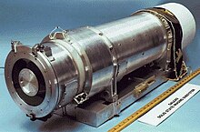
The SSI was an 800-by-800-pixel charge-coupled device (CCD) camera. The optical portion of the camera was a modified flight spare of the Voyager narrow-angle camera; a Cassegrain telescope. The CCD had radiation shielding a 10 mm (0.4 in) thick layer of tantalum surrounding the CCD except where the light enters the system. An eight-position filter wheel was used to obtain images at specific wavelengths. The images were then combined electronically on Earth to produce color images. The spectral response of the SSI ranged from about 400 to 1100 nm. The SSI weighed 29.7 kg (65 lb) and consumed, on average, 15 watts of power.
Near-infrared mapping spectrometer (NIMS)
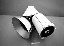
The NIMS instrument was sensitive to 0.7-to-5.2-micrometer wavelength infrared light, overlapping the wavelength range of the SSI. NIMS used a 229 mm (9 in) aperture reflecting telescope. The spectrometer used a grating to disperse the light collected by the telescope. The dispersed spectrum of light was focused on detectors of indium, antimonide and silicon. NIMS weighed 18 kg (40 lb) and used 12 watts of power on average.
Ultraviolet spectrometer / extreme ultraviolet spectrometer (UVS/EUV)
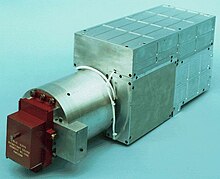
The Cassegrain telescope of the UVS had a 250 mm (9.8 in) aperture. Both the UVS and EUV instruments used a ruled grating to disperse light for spectral analysis. Light then passed through an exit slit into photomultiplier tubes that produced pulses of electrons, which were counted and the results sent to Earth. The UVS was mounted on Galileo's scan platform. The EUV was mounted on the spun section. As Galileo rotated, EUV observed a narrow ribbon of space perpendicular to the spin axis. The two instruments combined weighed about 9.7 kg (21 lb) and used 5.9 watts of power.
Photopolarimeter–radiometer (PPR)
The PPR had seven radiometry bands. One of these used no filters and observed all incoming radiation, both solar and thermal. Another band allowed only solar radiation through. The difference between the solar-plus-thermal and the solar-only channels gave the total thermal radiation emitted. The PPR also measured in five broadband channels that spanned the spectral range from 17 to 110 micrometers. The radiometer provided data on the temperatures of Jupiter's atmosphere and satellites. The design of the instrument was based on that of an instrument flown on the Pioneer Venus spacecraft. A 100 mm (4 in) aperture reflecting telescope collected light and directed it to a series of filters, and, from there, measurements were performed by the detectors of the PPR. The PPR weighed 5.0 kg (11.0 lb) and consumed about 5 watts of power.
Spun section
Dust-detector subsystem (DDS)
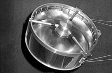
The dust-detector subsystem (DDS) was used to measure the mass, electric charge, and velocity of incoming particles. The masses of dust particles that the DDS could detect go from 10 to 10 grams. The speed of these small particles could be measured over the range of 1 to 70 kilometers per second (0.6 to 43.5 mi/s). The instrument could measure impact rates from 1 particle per 115 days (10 megaseconds) to 100 particles per second. Such data was used to help determine dust origin and dynamics within the magnetosphere. The DDS weighed 4.2 kg (9.3 lb) and used an average of 5.4 watts of power.
Energetic-particles detector (EPD)
The energetic-particles detector (EPD) was designed to measure the numbers and energies of ions and electrons whose energies exceeded about 20 keV (3.2 fJ). The EPD could also measure the direction of travel of such particles and, in the case of ions, could determine their composition (whether the ion is oxygen or sulfur, for example). The EPD used silicon solid-state detectors and a time-of-flight detector system to measure changes in the energetic particle population at Jupiter as a function of position and time. These measurements helped determine how the particles got their energy and how they were transported through Jupiter's magnetosphere. The EPD weighed 10.5 kg (23 lb) and used 10.1 watts of power on average.
Heavy-ion counter (HIC)
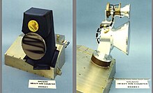
The HIC was, in effect, a repackaged and updated version of some parts of the flight spare of the Voyager cosmic-ray system. The HIC detected heavy ions using stacks of single crystal silicon wafers. The HIC could measure heavy ions with energies as low as 6 MeV (1 pJ) and as high as 200 MeV (32 pJ) per nucleon. This range included all atomic substances between carbon and nickel. The HIC and the EUV shared a communications link and, therefore, had to share observing time. The HIC weighed 8.0 kg (17.6 lb) and used an average of 2.8 watts of power.
Magnetometer (MAG)
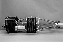
The magnetometer (MAG) used two sets of three sensors. The three sensors allowed the three orthogonal components of the magnetic field section to be measured. One set was located at the end of the magnetometer boom and, in that position, was about 11 m (36 ft) from the spin axis of the spacecraft. The second set, designed to detect stronger fields, was 6.7 m (22 ft) from the spin axis. The boom was used to remove the MAG from the immediate vicinity of Galileo to minimize magnetic effects from the spacecraft. However, not all these effects could be eliminated by distancing the instrument. The rotation of the spacecraft was used to separate natural magnetic fields from engineering-induced fields. Another source of potential error in measurement came from the bending and twisting of the long magnetometer boom. To account for these motions, a calibration coil was mounted rigidly on the spacecraft to generate a reference magnetic field during calibrations. The magnetic field at the surface of the Earth has a strength of about 50,000 nT. At Jupiter, the outboard (11 m) set of sensors could measure magnetic field strengths in the range from ±32 to ±512 nT, while the inboard (6.7 m) set was active in the range from ±512 to ±16,384 nT. The MAG experiment weighed 7.0 kg (15.4 lb) and used 3.9 watts of power.
Plasma subsystem (PLS)
The PLS used seven fields of view to collect charged particles for energy and mass analysis. These fields of view covered most angles from 0 to 180 degrees, fanning out from the spin axis. The rotation of the spacecraft carried each field of view through a full circle. The PLS measured particles in the energy range from 0.9 to 52,000 eV (0.14 to 8,300 aJ). The PLS weighed 13.2 kg (29 lb) and used an average of 10.7 watts of power.
Plasma-wave subsystem (PWS)
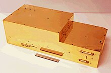
An electric dipole antenna was used to study the electric fields of plasmas, while two search coil magnetic antennas studied the magnetic fields. The electric dipole antenna was mounted at the tip of the magnetometer boom. The search coil magnetic antennas were mounted on the high-gain antenna feed. Nearly simultaneous measurements of the electric and magnetic field spectrum allowed electrostatic waves to be distinguished from electromagnetic waves. The PWS weighed 7.1 kg (16 lb) and used an average of 9.8 watts.
Galileo entry probe
 Diagram of the atmospheric entry probe's instruments and subsystems | |
| Mission type | Atmospheric probe |
|---|---|
| Operator | NASA |
| COSPAR ID | 1989-084E |
| SATCAT no. | 43337 |
| Mission duration | 61.4 minutes |
| Distance travelled | 83 million km (52 million mi) |
| Spacecraft properties | |
| Manufacturer | Hughes Aircraft Company |
| BOL mass | 340 kg (750 lb) |
| Payload mass | 29 kg (64 lb) |
| Power | 580 watts |
| Start of mission | |
| Launch date | October 18, 1989, 16:53:40 UTC |
| Rocket | Space Shuttle Atlantis STS-34/IUS |
| Launch site | Kennedy LC-39B |
| Deployed from | Galileo |
| Deployment date | July 12, 1995, 03:07 UTC |
| End of mission | |
| Last contact | December 7, 1995, 23:06:08 UTC |
| Jupiter atmospheric probe | |
| Atmospheric entry | December 7, 1995, 22:04:44 UTC |
| Impact site | 6°30′N 4°24′W / 6.5°N 4.4°W |
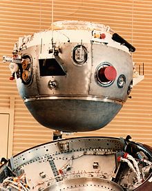
The atmospheric probe was built by Hughes Aircraft Company's Space and Communications Group at its El Segundo, California plant. It weighed 339 kilograms (747 lb) and was 86 centimeters (34 in) high.
Heat shield
Inside the probe's heat shield, the scientific instruments were protected from extreme heat and pressure during its high-speed journey into the Jovian atmosphere, entering at 48 kilometers per second (110,000 mph). Temperatures reached around 16,000 °C (29,000 °F). The ablative heat shield was made of carbon phenolic. NASA built a special laboratory, the Giant Planet Facility, to simulate the heat load, which was similar to the convective and radiative heating experienced by an ICBM warhead reentering the atmosphere.
Batteries
The probe's electronics were powered by 13 lithium sulfur dioxide batteries manufactured by Honeywell's Power Sources Center in Horsham, Pennsylvania. Each cell was the size of a D battery so existing manufacturing tools could be used. They provided a nominal power output of about 7.2-ampere hours capacity at a minimal voltage of 28.05 volts.
Scientific instruments
The probe included seven instruments for taking data on its plunge into Jupiter:
| Instrument | Function | Mass | Power consumption | Principal investigator | Organizations |
|---|---|---|---|---|---|
| Atmospheric structure instrument | Measuring temperature, pressure and deceleration | 4.1 kg (9.0 lb) | 6.3 W | Alvin Seiff | Ames Research Center and San Jose State University Foundation |
| Neutral mass spectrometer | Analyze the gas composition of the atmosphere | 13 kg (29 lb) | 29 W | Hasso Niemann | Goddard Space Flight Center |
| Helium Abundance Detector | An interferometer supporting atmospheric composition studies | 1.4 kg (3.1 lb) | 1.1 W | Ulf von Zahn | University of Bonn, University of Rostock |
| Nephelometer | Cloud location and cloud-particle observations | 4.8 kg (11 lb) | 14 W | Boris Ragent | Ames Research Center and San Jose State University Foundation |
| Net-flux radiometer | Measuring the difference between upward and downward radiant flux at each altitude | 3.0 kg (6.6 lb) | 7.0 W | L. Sromovsky | University of Wisconsin |
| Lightning and radio emission detector and energetic particles instrument | Measuring light and radio emissions associated with lightning, and fluxes of protons, electrons, alpha particles and heavy ions | 2.7 kg (6.0 lb) | 2.3 W | Louis Lanzerotti | Bell Laboratories, University of Florida and Federal Republic of Germany |
| Radio equipment | Measuring wind speeds and atmospheric absorption | David Atkinson | University of Idaho |
In addition, the probe's heat shield contained instrumentation to measure ablation during descent.
Termination
Lacking the fuel to escape Jupiter's gravity well, at the end of Galileo's life, the main spacecraft was deliberately crashed into Jupiter on September 21, 2003, to prevent forward contamination of possible life of Jupiter's moon Europa.
Names
The Galileo Probe had COSPAR ID 1989-084E while the orbiter had id 1989-084B. Names for the spacecraft include Galileo Probe or Jupiter Entry Probe abbreviated JEP. The related COSPAR IDs of the Galileo mission were:
- 1989-084A STS 34
- 1989-084B Galileo
- 1989-084C IUS (Orbus 21)
- 1989-084D IUS (Orbus 6E)
- 1989-084E Galileo Probe
See also
- Exploration of Jupiter
- List of missions to the outer planets
- Atmosphere of Jupiter
- List of spacecraft powered by non-rechargeable batteries
References
- ^ "The Final Day on Galileo" (Press release). Jet Propulsion Laboratory. September 21, 2003. Archived from the original on September 30, 2023.
- ^ "Galileo Jupiter Arrival" (PDF) (Press Kit). NASA / Jet Propulsion Laboratory. December 1995.
- ^ Taylor, Cheung & Seo 2002, p. 86.
- ^ "Galileo – Overview". NASA Solar System Exploration. Retrieved December 7, 2021.
- ^ "Jupiter: Facts – NASA Science". science.nasa.gov. NASA. Retrieved October 27, 2020.
- ^ Meltzer 2007, pp. 9–10.
- ^ Meltzer 2007, pp. 29–30.
- ^ Meltzer 2007, pp. 32–33.
- ^ Dawson & Bowles 2004, pp. 190–191.
- ^ Meltzer 2007, pp. 30–32.
- ^ "NASA's 50 Year Men and Women". NASA. Archived from the original on March 19, 2010. Retrieved October 28, 2020.
- ^ Meltzer 2007, p. 38.
- ^ "Galileo In Depth". NASA. Retrieved December 6, 2020.
- ^ Meltzer 2007, pp. 68–69.
- ^ Beyer, O'Connor & Mudgway 1992.
- ^ Meltzer 2007, p. 78.
- ^ Carr, Jeffrey (November 10, 1988). "Four New Shuttle Crews Named (STS-32, STS-33, STS-34, STS-35)" (PDF) (Press release). NASA. 88-049. Archived from the original (PDF) on February 25, 2017. Retrieved November 5, 2020.
- ^ Broad, William J. (October 10, 1989). "Groups Protest Use of Plutonium on Galileo". The New York Times. Retrieved November 4, 2020.
- ^ Sagan, Carl (October 9, 1989). "Galileo: To Launch or not to Launch?". Archived from the original on January 26, 2021. Retrieved November 4, 2020.
- ^ "Mission Archives: STS-34". NASA. February 18, 2010. Retrieved January 7, 2017.
- ^ Sawyer, Kathy (October 17, 1989). "Galileo Launch Nears". The Washington Post. Retrieved November 5, 2020.
- ^ "PDS: Mission Information". NASA. Retrieved November 9, 2020.
- ^ "Galileo Travels 292,500 Miles Toward Venus". The Washington Post. Retrieved November 5, 2020.
- ^ Siewiorek & Swarz 1998, p. 683.
- ^ Tomayko 1988, pp. 198–199.
- ^ Tomayko 1988, pp. 193–198.
- ^ "Galileo Engineering". RESA. Archived from the original on June 13, 2008.
- ^ Tomayko 1988, pp. 198–201.
- ^ Tomayko 1988, p. 199.
- ^ Tomayko 1988, p. 110.
- ^ Tomayko 1988, pp. 190–198.
- ^ "What's in an RTG?". NASA. Archived from the original on April 11, 2010. Retrieved May 15, 2011.
- ^ Bennett, Hemler & Schock 1994, p. 4.
- ^ "Galileo FAQ – Galileo's Antennas". jpl.nasa.gov. NASA / JPL. Archived from the original on May 28, 2010. Retrieved May 15, 2011.
- ^ "Solid-State Imaging (SSI)". NASA. Retrieved November 19, 2020.
- ^ "SSI – Solid State Imaging". NASA. Archived from the original on July 1, 2010. Retrieved May 15, 2011.
- ^ "SSI Imaging Team". NASA. Archived from the original on August 2, 2009.
- ^ "NIMS – Near-Infrared Mapping Spectrometer". NASA. Archived from the original on May 28, 2010. Retrieved May 15, 2011.
- ^ "NIMS Team". UCLA. Archived from the original on October 10, 1999.
- ^ "EUVS – Extreme Ultraviolet Spectrometer". NASA. Archived from the original on June 5, 2010. Retrieved May 15, 2011.
- ^ "EUV Team". University of Colorado at Boulder. Archived from the original on August 14, 2010.
- ^ "PPR – Photopolarimeter-Radiometer". NASA. Archived from the original on June 14, 2010. Retrieved May 15, 2011.
- ^ "PPR Team". Lowell Observatory. Archived from the original on July 21, 2004.
- ^ "DDS – Dust Detector Subsystem". NASA. Archived from the original on June 19, 2010. Retrieved May 15, 2011.
- ^ "Cosmic Dust: Messengers from Distant Worlds". High Energy Stereoscopic System. Archived from the original on February 10, 2007. Retrieved December 10, 2012.
DSI via Stuttgart University
- ^ "EPD – Energetic Particles Detector". NASA. Archived from the original on June 21, 2010. Retrieved May 15, 2011.
- ^ "Galileo EPD". Johns Hopkins University Applied Physics Laboratory. Retrieved December 5, 2020.
- ^ "HIC – Heavy Ion Counter". NASA. Archived from the original on July 2, 2010. Retrieved May 15, 2011.
- ^ "HIC Team". Caltech. Archived from the original on December 2, 2005. Retrieved December 5, 2020.
- ^ "MAG – Magnetometer". NASA. Archived from the original on February 18, 2010. Retrieved May 15, 2011.
- ^ "MAG Team". UCLA. Archived from the original on July 21, 2004.
- ^ "PLS – Plasma Subsystem". NASA. Archived from the original on June 21, 2010. Retrieved May 15, 2011.
- ^ "PLS Team". University of Iowa. Archived from the original on February 10, 2007..
- ^ "PWS – Plasma Wave Subsystem". NASA. Archived from the original on December 13, 2009. Retrieved May 15, 2011.
- ^ "Galileo PWS". University of Iowa. Retrieved December 5, 2020.
- ^ "Galileo Jupiter Atmospheric Probe". science.nasa.gov. NASA. Retrieved August 20, 2024.
- ^ "Hughes Science/Scope Press Release and Advertisement". FlightGlobal.com. Archived from the original on January 12, 2012. Retrieved May 15, 2011.
- ^ "Galileo Arrives at Kennedy Space Center". jpl.nasa.gov (Press release). NASA / JPL. May 17, 1989. Retrieved March 6, 2021.
- ^ D. Isbell; D. Morse (January 22, 1996). "Galileo Probe Science Results". NASA / JPL. Archived from the original on January 28, 2016. Retrieved March 4, 2016.
- ^ Milos 1997.
- ^ Laub & Venkatapathy 2003, pp. 1–9.
- ^ Bernard Laub (October 19, 2004). "Development of New Ablative Thermal Protection Systems (TPS)". NASA / Ames. Archived from the original on October 19, 2006. Retrieved December 12, 2006.
- ^ Meltzer 2007, p. 118.
- ^ Hofland, Stofel & Taenaka 1996, p. 9.
- ^ Blagdon 1980, p. 83.
- ^ Meltzer 2007, p. 122.
- ^ "Experiments on Galileo Probe". nssdc.gsfc.nasa.gov. NASA. Retrieved January 18, 2009.
- ^ Milos 1997, pp. 705–713.
- ^ Fraser Cain (September 22, 2003). "Galileo Plunges Into Jupiter". Universe Today. Retrieved February 10, 2022.
- ^ Badescu & Zacny 2018, p. 836.
- ^ Ritter et al. 2006, p. 6.
- ^ "Space Launch 1989-084". lib.cas.cz (in Czech). Knihovna Akademie věd ČR. Retrieved December 3, 2018.
Bibliography
- Badescu, Viorel; Zacny, Kris (2018). Outer Solar System: Prospective Energy and Material Resources. Springer. ISBN 978-3-319-73845-1. OCLC 1042249198.
- Blagdon, L. (1980). "Galileo Lithium SO2". The 1979 Goddard Space Flight Center Battery Workshop (PDF). Goddard Space Flight Center: NASA. pp. 83–95. Retrieved March 7, 2021.
- Beyer, P. E.; O'Connor, R. C.; Mudgway, D. J. (May 15, 1992). "Galileo Early Cruise, Including Venus, First Earth, and Gaspra Encounters" (PDF). The Telecommunications and Data Acquisition Report: 265–281. TDA Progress Report 42-109. Retrieved March 6, 2021.
- Bennett, Gary L.; Hemler, Richard J.; Schock, Alfred (October 9–14, 1994). Development and Use of the Galileo and Ulysses Power Sources. 45th Congress of the International Astronautical Federation. Jerusalem, Israel. Retrieved December 7, 2020.
- Dawson, Virginia; Bowles, Mark (2004). Taming Liquid Hydrogen: The Centaur Upper Stage Rocket (PDF). The NASA History Series. Washington, DC: NASA. SP-4230. Retrieved October 1, 2020.
- Hofland, L. M.; Stofel, E. J.; Taenaka, R. K. (1996). "Galileo Probe Lithium-Sulfur Dioxide Cell Life Testing". Proceedings of 11th Annual Battery Conference on Applications and Advances. Long Beach, California. pp. 9–14. doi:10.1109/BCAA.1996.484963. ISBN 0-7803-2994-5.
- Laub, B.; Venkatapathy, E. (October 6–9, 2003). "Thermal Protection System Technology and Facility Needs for Demanding Future Planetary Missions". International Workshop on Planetary Probe Atmospheric Entry and Descent Trajectory Analysis and Science (PDF). Lisbon, Portugal: University of Idaho. pp. 1–9. Archived from the original (PDF) on January 8, 2007. Retrieved December 12, 2006.
- Meltzer, Michael (2007). Mission to Jupiter: A History of the Galileo Project (PDF). The NASA History Series. Washington, DC: NASA. OCLC 124150579. SP-4231. Retrieved January 19, 2021.
- Milos, Frank S. (1997). "Galileo Probe Heat Shield Ablation Experiment". Journal of Spacecraft and Rockets. 34 (6): 705–713. Bibcode:1997JSpRo..34..705M. doi:10.2514/2.3293. ISSN 1533-6794.
- Ritter, H.; Mazoue, F.; Santovincenzo, A.; Atzei, A. (2006). "Jupiter Entry Probe Feasibility Study from the ESTEC CDF Team: Heat Flux Evaluation & TPS Definition". Thermal Protection Systems and Hot Structures. 631: 6. Bibcode:2006ESASP.631E...6R.
- Siddiqi, Asif A. (2018). Beyond Earth: A Chronicle of Deep Space Exploration, 1958–2016 (PDF). The NASA History Series (second ed.). Washington, DC: NASA History Program Office. ISBN 978-1-62683-042-4. LCCN 2017059404. SP-4041. Retrieved October 29, 2020.
- Siewiorek, Daniel; Swarz, Robert S. (1998). Reliable Computer Systems. Natick, Massachusetts: A K Peters. ISBN 1-56881-092-X. OCLC 245700546.
- Taylor, Jim; Cheung, Kar-Ming; Seo, Dongae (July 2002). Galileo Telecommunications (PDF). DESCANSO Design and Performance Summary Series. Washington, DC: NASA. Retrieved November 15, 2020.
- Tomayko, James E. (March 1988). Computers in Spaceflight: The NASA Experience (PDF) (Report). NASA History Office. Archived from the original (PDF) on February 12, 2024. Retrieved October 29, 2020.
External links
- Galileo mission site by NASA's Solar System Exploration
- Galileo legacy site by NASA's Solar System Exploration
- Galileo Satellite Image Mosaics Archived June 2, 2016, at the Wayback Machine by Arizona State University
- Galileo image album by Kevin M. Gill
- Early probe results report
- Galileo Probe NASA Space Science Data Coordinated Archive
